
Mechanical Stack-Up, Actuator Actuation Mechanics, Drift Compensation, and Environmental Protection Guidelines
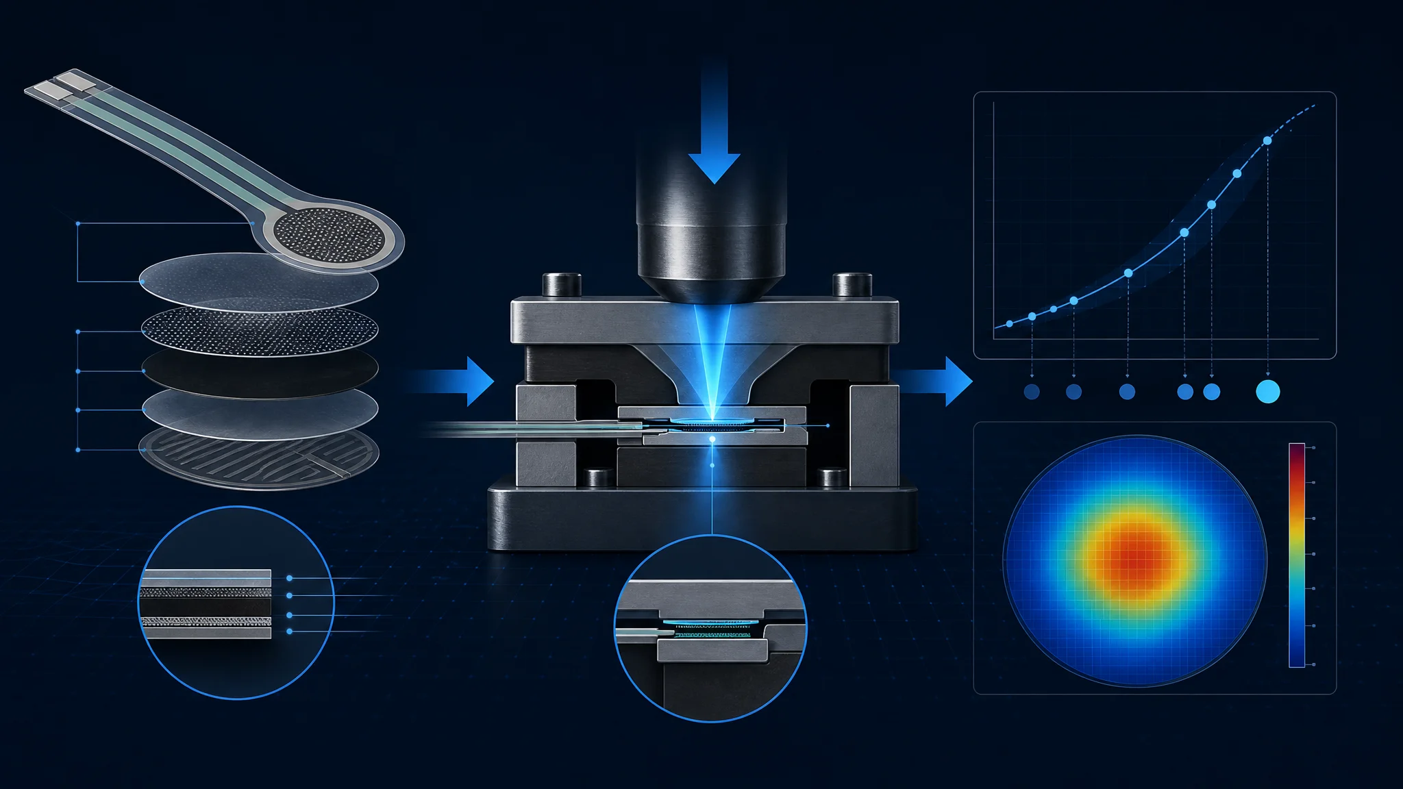 Engineering illustration · FSRTEK technical reference
1. Defining the Realistic Capability Boundaries of FSRs
Before designing an FSR product, engineers must align application requirements with the physical capabilities of polymer thick-film technology:
| Ideal FSR Applications (Best-in-Class) | Unsuitable Applications (Requires Load Cell) |
|---|---|
| Touch / contact presence & threshold triggering | Legal-for-trade commercial weighing scales |
| Relative force change & dynamic impact rate | High-precision static force measurement ($<1%$ over hours) |
| Tactile pressure distribution mapping & balance analysis | Metrology-grade laboratory instrumentation |
| Ergonomic grip force & multi-level human-machine input | Uncompensated outdoor environments with $-40^circtext{C} sim +120^circtext{C}$ swings |
2. Mechanical Stack-Up & Actuator Puck Design
The mechanical interface directly dictates measurement repeatability. Applying force directly with soft human skin produces highly variable readings due to changing contact area. Repeatable integration demands a defined mechanical stack-up:
- Rigid Backing Substrate: The FSR must be mounted on a smooth, flat, unyielding surface (aluminum plate, FR4 PCB, or rigid injection-molded chassis). Flexible or warped backing introduces parasitic bending strain that the sensor registers as false force.
- Actuator Puck (Plunger): Utilize a slightly compliant elastomer puck (e.g. 50~70 Shore A polyurethane or silicone) positioned directly over the active sensing area. The puck must be sized slightly smaller (80% ~ 90% of active diameter) than the sensing boundary to avoid edge-clamping shear forces.
- Pre-Load Management: A small mechanical pre-load (1% ~ 3% of full-scale force) holds the stack-up in intimate contact, eliminating dead-band hysteresis and ensuring instantaneous zero-delay response to dynamic loads.
3. Static Creep, Hysteresis & Dynamic Drift Compensation
Polymer thick films exhibit natural viscoelastic relaxation under sustained mechanical load, known as Static Creep (conductance slowly drifts upward under constant force over minutes). FSRTEK engineers utilize three standard compensation strategies:
1. Logarithmic Time-Decay Creep Compensation
Under static load, creep follows an empirical logarithmic trajectory: $Delta F_{creep}(t) = alpha cdot ln(1 + beta t)$. Software tracks the continuous dwell time of active force and subtracts the estimated creep offset in real time.
2. Dynamic AC Filtering for Transient Events
For athletic strikes, musical key hits, and robotic tap detection, high-pass filter the force signal ($f_c approx 0.5,text{Hz}$). This eliminates 100% of slow baseline drift while preserving crisp, high-frequency impact dynamics.
3. Periodic Zero Baseline Re-Tare
Whenever the signal drops below a defined touch threshold for more than $500,text{ms}$, automatically re-tare the zero conductance baseline $G_0$.
4. Calibration Procedures for Production & Field Deployment
| Calibration Class | Procedure & Equipment | Achievable Accuracy |
|---|---|---|
| 1-Point Calibration (Factory Quick-Set) | Apply single nominal mid-scale load (e.g., $1,text{kg}$). Calibrate gain multiplier $k = frac{F_{target}}{V_{meas}}$. Fast and effective for threshold triggering. | $pm 10% sim pm 15%$ |
| 3-Point Piecewise Calibration (Standard) | Apply tare ($0,text{kg}$), mid-range ($1,text{kg}$), and full-scale ($5,text{kg}$) loads using a pneumatic test stand. Store 3-segment linear slopes in EEPROM/Flash. | $pm 3% sim pm 6%$ |
| Automated Multi-Point Thermal Calibration | Motorized load cell + environmental chamber cycling across $10^circtext{C}, 25^circtext{C}, 45^circtext{C}$. Generates a 2D polynomial look-up matrix ($F = f(V, T)$). | $pm 1.5% sim pm 3%$ |
Need an Engineering Review?
Share your sensing requirement, drawing or application target with the FSRTEK team.
Contact Application Engineers