
End-to-End System Architecture: Sensor Interfacing, Multi-Layer Buffering, Calibration Transforms, and Real-Time Visualization
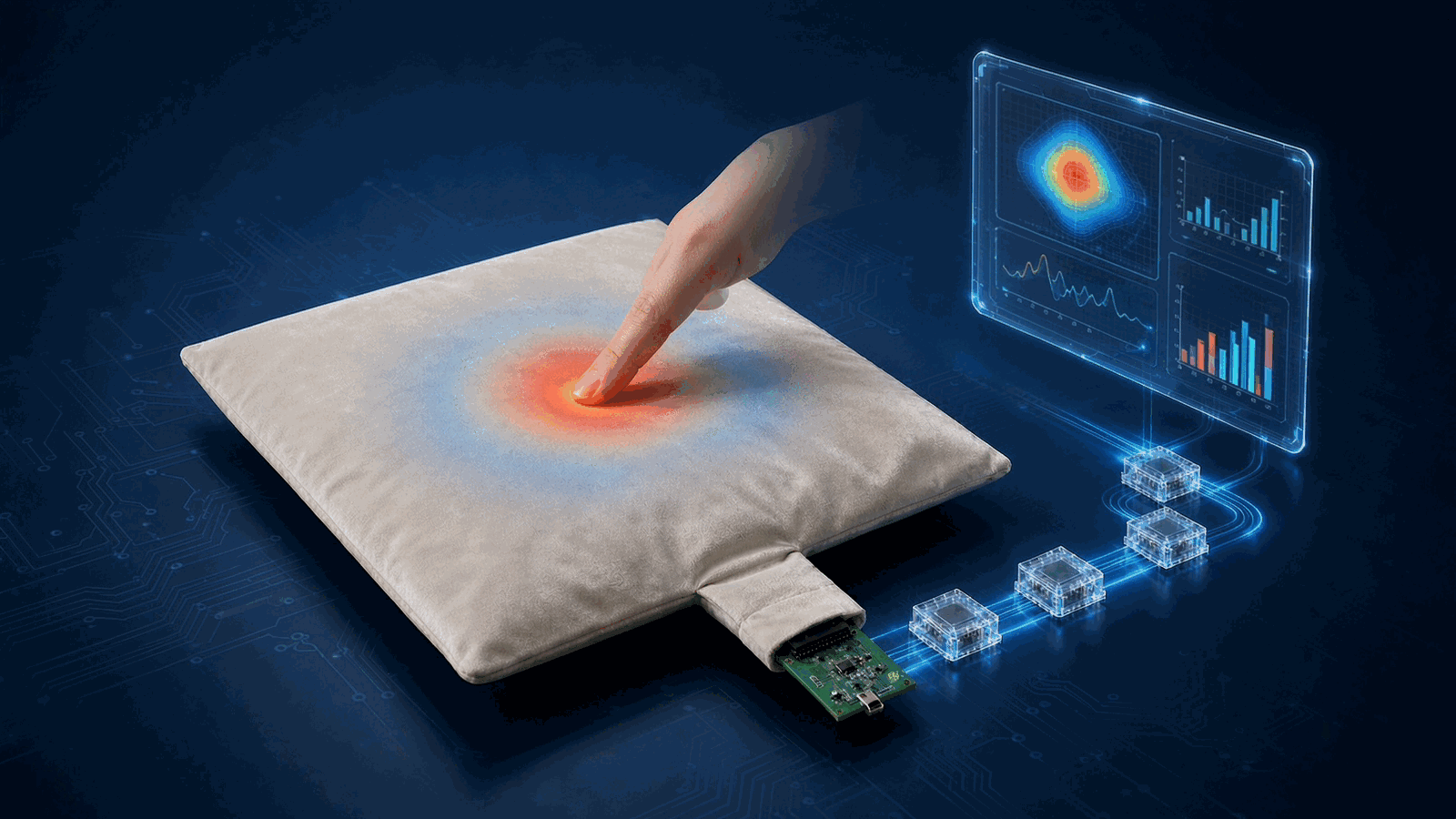 Engineering illustration · FSRTEK technical reference
1. Architectural Overview: The 5-Layer Signal Chain
Directly coupling ADC read routines to user-interface graphics leads to dropped packets, timing jitter, and software fragility. FSRTEK recommends a modular, decoupled architecture structured into five distinct operational tiers:
[Layer 2] Adapter & Ingestion: UART / USB CDC / BLE GATT / Ethernet → CRC Packet Unpacker
[Layer 3] Data Bus & Circular Buffer: Lock-Free FIFO Buffer → Millisecond Hardware Timestamping
[Layer 4] Digital Signal Processing: Noise Filtering → Non-Linear Calibration Transform → Feature Extraction
[Layer 5] Application & UI Layer: Heatmap Canvas → Real-Time Curves → Alarm Logic → SDK / API Export
2. Ingestion & Packet Framing Protocol
To guarantee zero packet loss over serial or wireless channels, edge acquisition boards stream fixed-frame binary packets with robust boundary detection:
| Byte Offset | Field Name | Length | Description |
|---|---|---|---|
| 0x00 – 0x01 | Header | 2 Bytes | Synchronization word (e.g. 0xAA 0x55) |
| 0x02 | Device ID | 1 Byte | Hardware node identifier / Matrix zone index |
| 0x03 – 0x06 | Timestamp | 4 Bytes | Microsecond hardware counter (rollover protected) |
| 0x07 – 0x08 | Payload Length | 2 Bytes | Number of raw ADC channels ($N$) |
| 0x09 – $0x09+2N$ | ADC Data | $2N$ Bytes | 12-bit / 16-bit raw ADC code array |
| End-1 to End | Checksum | 2 Bytes | CRC-16-CCITT integrity verification |
3. Calibration & Non-Linear Transformation Pipeline
Raw ADC integer codes are converted into calibrated physical force units ($text{N}$, $text{g}$, $text{kg}$, or $text{kPa}$) through a standardized numerical transformation pipeline:
- Voltage / Conductance Conversion: Convert raw ADC code $D_{adc}$ into measured conductance $G_{meas} = frac{1}{R_{FSR}}$.
- Baseline Zero Subtraction: $G_{active} = max(0, G_{meas} – G_{tare})$, removing initial mechanical pre-load offsets.
- Multi-Segment Piecewise Linear (PWL) Interpolation: Because FSR response varies across light, medium, and saturation regimes, a 5-point to 10-point piecewise linear lookup table provides high-speed conversion on embedded MCUs without floating-point polynomial overhead:
$$F(G) = F_k + frac{F_{k+1} – F_k}{G_{k+1} – G_k} cdot (G – G_k) quad text{for } G in [G_k, G_{k+1})$$
- Power-Law Curve Fitting (High-Level SDK): For PC/cloud analytics, apply a calibrated three-parameter power-law fit: $F = a cdot G^b + c$.
4. Multi-Tier Feature Extraction & Event Detection
The processing layer extracts actionable engineering parameters in real time:
- Peak Force & Impact Impulse: Integration of force over contact duration $J = int_{t_0}^{t_1} F(t),dt$, essential for athletic strike and crash analytics.
- Center of Force (CoF) / Center of Pressure (CoP): Dynamic 2D spatial coordinate calculation for balance plates and smart insoles:
$$X_{CoP} = frac{sum (x_i cdot F_i)}{sum F_i}, quad Y_{CoP} = frac{sum (y_i cdot F_i)}{sum F_i}$$
- Threshold Trigger & Debounce Engine: Dual-threshold Schmitt trigger logic prevents chattering on mechanical contact boundaries.
Need an Engineering Review?
Share your sensing requirement, drawing or application target with the FSRTEK team.
Contact Application Engineers