
Matrix Scanning Topologies, Zero-Potential Virtual Ground Clamping, and Real-Time De-Ghosting Algorithms
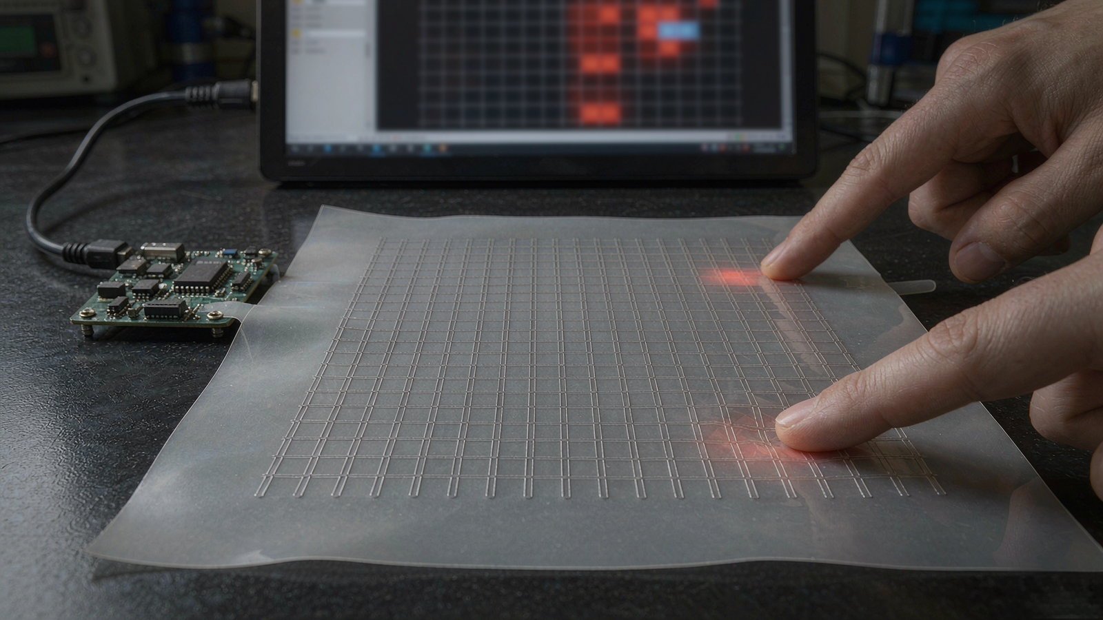 Engineering illustration · FSRTEK technical reference
1. The Root Cause of Ghost Points in Matrix Arrays
An $M times N$ tactile pressure array consists of orthogonal intersecting drive (Row) and sense (Column) electrodes with a continuous piezoresistive layer sandwiched between them. When three nodes (e.g., $(R_1, C_1)$, $(R_1, C_2)$, $(R_2, C_1)$) are compressed simultaneously, a parasitic series-parallel sneak current pathway forms through unpressed node $(R_2, C_2)$:
$$text{Sneak Path: } R_2 longrightarrow (R_2, C_1) longrightarrow (R_1, C_1) longrightarrow (R_1, C_2) longrightarrow C_2$$
Without active circuit clamping, the ADC reads a phantom voltage on $(R_2, C_2)$ even though zero mechanical force is applied at that intersection. This false reading is a Ghost Point.
2. Hardware Countermeasure: Zero-Potential Virtual Ground Clamping
The industry benchmark hardware architecture for eliminating cross-talk is the Zero-Potential Scanning Method, utilizing operational amplifier virtual grounds:
- Selected Row ($R_{active}$): Driven with a stable excitation voltage $+V_{ref}$.
- Unselected Rows ($R_{inactive}$): Actively clamped to analog ground ($0text{V}$) via low-$R_{on}$ analog multiplexer switches.
- All Column Channels ($C_1 dots C_N$): Connected directly to inverting inputs of transimpedance amplifiers. Negative feedback holds every column at virtual ground ($V_- = 0text{V}$).
Why Virtual Ground Eliminates Ghost Current
Because all unselected rows are at $0text{V}$ and all column lines are held at virtual $0text{V}$, the potential difference across every unselected sensor node is identically zero:
$$Delta V_{unselected} = V_{row, inactive} – V_{col, virtual} = 0text{V} – 0text{V} = 0text{V}$$
With zero voltage drop across unselected intersections, sneak currents are physically eliminated at the hardware layer, preventing ghost signals regardless of how many contact points are depressed simultaneously.
3. High-Speed Scanning Architecture & Frame Rate Optimization
Capturing dynamic impacts (such as athletic foot strikes or rapid robot grasping) requires continuous high frame rates ($100,text{Hz} sim 500,text{Hz}$ across matrices with 256 to 4,096 nodes):
- Parallel Column Sampling: Drive one row at a time while sampling all $N$ columns simultaneously using multi-channel synchronized ADCs or dedicated matrix AFE ASICs.
- Settle Time vs. Trace Capacitance: Flexible PET matrix arrays exhibit distributed trace capacitance ($C_{trace} approx 50,text{pF} sim 500,text{pF}$). Row excitation pulses must allow sufficient RC settling time ($t_{settle} ge 3 tau$) before ADC sample-and-hold triggers.
- Dynamic Line Clamping: Fast analog switches (e.g. ADG732, TMUX1208) with $t_{on} < 50,text{ns}$ maintain sharp scanning transitions.
4. Software Post-Processing & Artifact Rejection Pipeline
Even with hardware zero-potential clamping, minor baseline offsets and edge transients require structured digital filtering:
- Spatial 2D Median Filtering: $3 times 3$ kernel to suppress isolated single-pixel thermal/ADC noise spikes while preserving sharp pressure boundaries.
- 2D Gaussian Surface Smoothing: Sub-pixel interpolation ($sigma = 0.8 sim 1.2$) to reconstruct smooth, continuous pressure gradient heatmaps.
- Dynamic Zero-Tracking (DZT): Continuously tracks slow temperature and humidity drift on unloaded nodes and updates the per-node baseline matrix in real time.
- Connected-Component Labeling (CCL): Groups contiguous active nodes into discrete contact blobs, computing individual center-of-pressure (CoP) coordinates and total contact force per object.
Need an Engineering Review?
Share your sensing requirement, drawing or application target with the FSRTEK team.
Contact Application Engineers